Engine mounted instrument panel with four position switch, overspeed shutdown notification light, emergency stop notificationlight, graphical display unit for analog or digital display of: oil andfuel pressure, oil and fuel filter differential, system DC voltage,exhaust and water temperature, air inlet restriction, servicemeter, engine speed, fuel consumption (total and instantaneous)
LUBE SYSTEM
Top mounted crankcase breather, RH oil filter, RH oil filler,gear type oil pump, deep sump oil pan, recommended use ofCaterpillar Diesel Engine Oil 10W30 or 15W40
A-III Electronic Monitoring System provides customer programmableengine de-ration strategies to protect against adverse operatingconditions
Emergency stop push button (located in Electronic Instrument Panel)Safety shutoff protection for oil pressure and water temperature, overspeed protection
GENERAL
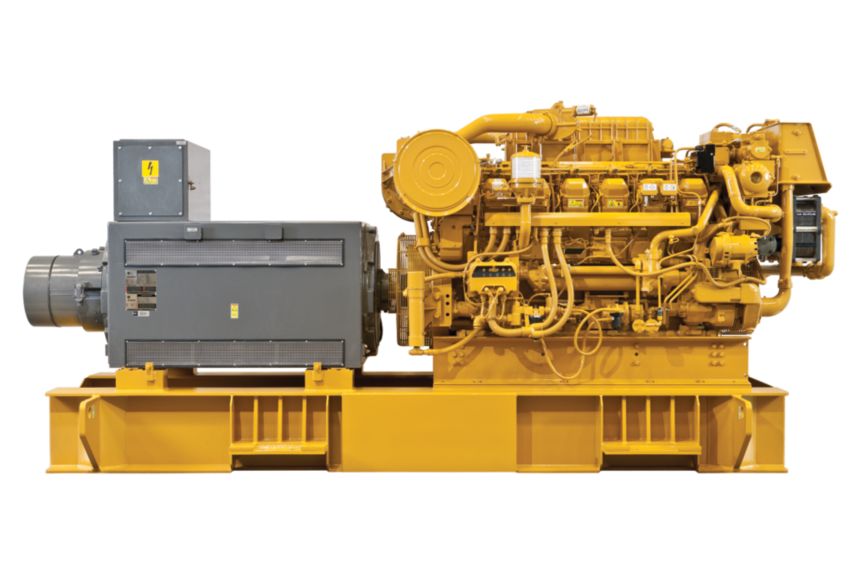
Vibration damper and guardPaint, Caterpillar Yellow engine with black rails.Lifting eyes
3512C Optional Equipment
AIR INLET SYSTEM
Air Cleaner Removal
Remote Air Inlet Adapters
CHARGING SYSTEM
Battery Chargers
Charging Alternators
CONTROL SYSTEM
Load Sharing module
Local speed throttle control
COOLING SYSTEM
Water level switch gauge
Coolant level sensors
Connections
Keel Cooling Conversions
Radiator cooling conversion
Heat exchangers
Auxiliary water pumps
Sea water pump removal
Air separator
EXHAUST SYSTEM
Exhaust outlet
Flexible fittings
Elbows
Flanges
Flange and exhaust expanders
Mufflers
FUEL SYSTEM
Fuel Cooler
Fuel priming pumps
Flexible fuel lines
Rigid Fuel Lines
Primary fuel filter
Fuel level switch
GENERATORS AND GENERATOR ATTACHMENTS
INSTALLED GENERATOR ARRANGEMENTS F/MAR AUX ENGINES
INSTALLED GENERATOR ARRANGEMENTS F/MAR AUX ENGINES
Engine mounted instrument panel with four position switch, overspeed shutdown notification light, emergency stop notificationlight, graphical display unit for analog or digital display of: oil andfuel pressure, oil and fuel filter differential, system DC voltage,exhaust and water temperature, air inlet restriction, servicemeter, engine speed, fuel consumption (total and instantaneous)
LUBE SYSTEM
Top mounted crankcase breather, RH oil filter, RH oil filler,gear type oil pump, deep sump oil pan, recommended use ofCaterpillar Diesel Engine Oil 10W30 or 15W40
A-III Electronic Monitoring System provides customer programmableengine de-ration strategies to protect against adverse operatingconditions
Emergency stop push button (located in Electronic Instrument Panel)Safety shutoff protection for oil pressure and water temperature, overspeed protection
GENERAL
Vibration damper and guardPaint, Caterpillar Yellow engine with black rails.Lifting eyes
3512C Optional Equipment
AIR INLET SYSTEM
Air Cleaner Removal
Remote Air Inlet Adapters
CHARGING SYSTEM
Battery Chargers
Charging Alternators
CONTROL SYSTEM
Load Sharing module
Local speed throttle control
COOLING SYSTEM
Water level switch gauge
Coolant level sensors
Connections
Keel Cooling Conversions
Radiator cooling conversion
Heat exchangers
Auxiliary water pumps
Sea water pump removal
Air separator
EXHAUST SYSTEM
Exhaust outlet
Flexible fittings
Elbows
Flanges
Flange and exhaust expanders
Mufflers
FUEL SYSTEM
Fuel Cooler
Fuel priming pumps
Flexible fuel lines
Rigid Fuel Lines
Primary fuel filter
Fuel level switch
GENERATORS AND GENERATOR ATTACHMENTS
INSTALLED GENERATOR ARRANGEMENTS F/MAR AUX ENGINES
INSTALLED GENERATOR ARRANGEMENTS F/MAR AUX ENGINES