Specifications

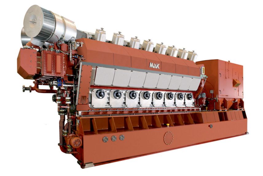
VM 32 C

Specifications

Minimum Rating5754 kWe (7200 kVA)
Maximum Rating7672 kWe (9600 kVA)
Configuration12,16 Cylinder
Bore320 mm12.6 in
Stroke460 mm18.11 in
Swept Volume37 l/cyl2257.88 in³
Emissions/Fuel StrategyEPA Tier 2 & IMO II
Height4639 mm (182.6 in)
Length10703 mm - 12149 mm (421.4 in - 478.3 in)
Weight120.0 t - 140.0 t (264554 lbs - 308647 lbs)
Width3526 mm ( 138.8 in)

VM 32 C Standard Equipment

  • Air Inlet System
    • Air intake silencer / filter
  • Control System
    • Load sharing unit (for multiple engine plant only)
    • Protection system (external cabinet)
    • Serial link interface (MODbus / canbus)
    • Speed governor
  • Cooling System
    • Electric cooling water preheater
    • HT cooling water pump (engine driven)
    • 2-stage charge air cooler
  • Exhaust System
    • Exhaust gas expansion joint
    • Exhaust gas insulated manifolds
    • Turbocharger at counter-flywheel end
  • Fuel System
    • Fuel circulating pump (electric driven / for MDO/MGO only)
    • Fuel indicator filter
    • Fuel pressure valve (separate / for MDO/MGO only)
  • Instrumentation
    • Control push buttons and lamps
    • Emergency stop lever
    • Local control panel
    • Pressure and temperature indicator
  • Lube System
    • Engine with dry sump
    • Lube oil plate cooler (separate)
    • Lube oil pump (engine driven)
    • Lube oil safety filter
    • Lube oil self-cleaning filter (separate)
    • Oil sump in base frame
    • Pre-lubricating oil pump (electric driven / fitted on base frame)
    • Pressure regulating valve
  • Mounting System
    • Engine resiliently mounted on base frame, base frame mounted rigidly
    • Flexible pipe connections
    • High flexible coupling
  • Starting System
    • Electrical barring device
    • Starting air valve
  • General
    • Engine, flexible coupling and generator mounted on a common base frame
    • Flywheel cover
    • Lifting device (rental)
    • Torsional Vibration Calculation (TVC)

VM 32 C Optional Equipment

  • Air Inlet System
    • Air inlet shut-off valve
    • Air intake transition piece
    • Expansion joint
    • Silencer / filter
  • Control System
    • Electronic speed governor
    • Engine alarm system
    • Remote indicators (start air pressure, engine speed, etc.)
    • Starter for electric driven pumps
    • 24 DC UPS
  • Cooling System
    • CW piping for generator cooling on base frame
    • CW piping for lubricating oil cooler on base frame
    • FW/SW plate cooler
    • HT cooling water pump (electric driven)
    • LT cooling water pump (electric driven)
    • Sea water cooling pump (electric driven)
    • Temperature control valve
  • Exhaust System
    • Silencer (with or without spark arrester)
  • Fuel System
    • Fuel oil cooler
    • HFO final preheater
    • HFO pressure regulating valve
    • HFO self-cleaning automatic filter
    • HFO supply and booster pumps (electric driven)
    • HFO treatment and supply modules
    • HFO viscosity control device
    • Mixing tank
  • Lube System
    • Lube oil centrifuge
    • Lube oil pump (electric driven)
    • Lube oil treatment and combined modules
    • Temperature control valve
  • Mounting System
    • Resilient mounting on base frame
  • Starting System
    • Starting air compressor
    • Starting air receiver
  • General
    • Generator customer supply

Specifications

Minimum Rating5754 kWe (7200 kVA)
Maximum Rating7672 kWe (9600 kVA)
Configuration12,16 Cylinder
Bore320 mm12.6 in
Stroke460 mm18.11 in
Swept Volume37 l/cyl2257.88 in³
Emissions/Fuel StrategyEPA Tier 2 & IMO II
Height4639 mm (182.6 in)
Length10703 mm - 12149 mm (421.4 in - 478.3 in)
Weight120.0 t - 140.0 t (264554 lbs - 308647 lbs)
Width3526 mm ( 138.8 in)

Equipment

VM 32 C Standard Equipment

  • Air Inlet System
    • Air intake silencer / filter
  • Control System
    • Load sharing unit (for multiple engine plant only)
    • Protection system (external cabinet)
    • Serial link interface (MODbus / canbus)
    • Speed governor
  • Cooling System
    • Electric cooling water preheater
    • HT cooling water pump (engine driven)
    • 2-stage charge air cooler
  • Exhaust System
    • Exhaust gas expansion joint
    • Exhaust gas insulated manifolds
    • Turbocharger at counter-flywheel end
  • Fuel System
    • Fuel circulating pump (electric driven / for MDO/MGO only)
    • Fuel indicator filter
    • Fuel pressure valve (separate / for MDO/MGO only)
  • Instrumentation
    • Control push buttons and lamps
    • Emergency stop lever
    • Local control panel
    • Pressure and temperature indicator
  • Lube System
    • Engine with dry sump
    • Lube oil plate cooler (separate)
    • Lube oil pump (engine driven)
    • Lube oil safety filter
    • Lube oil self-cleaning filter (separate)
    • Oil sump in base frame
    • Pre-lubricating oil pump (electric driven / fitted on base frame)
    • Pressure regulating valve
  • Mounting System
    • Engine resiliently mounted on base frame, base frame mounted rigidly
    • Flexible pipe connections
    • High flexible coupling
  • Starting System
    • Electrical barring device
    • Starting air valve
  • General
    • Engine, flexible coupling and generator mounted on a common base frame
    • Flywheel cover
    • Lifting device (rental)
    • Torsional Vibration Calculation (TVC)

VM 32 C Optional Equipment

  • Air Inlet System
    • Air inlet shut-off valve
    • Air intake transition piece
    • Expansion joint
    • Silencer / filter
  • Control System
    • Electronic speed governor
    • Engine alarm system
    • Remote indicators (start air pressure, engine speed, etc.)
    • Starter for electric driven pumps
    • 24 DC UPS
  • Cooling System
    • CW piping for generator cooling on base frame
    • CW piping for lubricating oil cooler on base frame
    • FW/SW plate cooler
    • HT cooling water pump (electric driven)
    • LT cooling water pump (electric driven)
    • Sea water cooling pump (electric driven)
    • Temperature control valve
  • Exhaust System
    • Silencer (with or without spark arrester)
  • Fuel System
    • Fuel oil cooler
    • HFO final preheater
    • HFO pressure regulating valve
    • HFO self-cleaning automatic filter
    • HFO supply and booster pumps (electric driven)
    • HFO treatment and supply modules
    • HFO viscosity control device
    • Mixing tank
  • Lube System
    • Lube oil centrifuge
    • Lube oil pump (electric driven)
    • Lube oil treatment and combined modules
    • Temperature control valve
  • Mounting System
    • Resilient mounting on base frame
  • Starting System
    • Starting air compressor
    • Starting air receiver
  • General
    • Generator customer supply

Related Products

Model.GetDictionaryValue(